


|
|
|
This originally started out as a 37amp alternator from the late 60's to early 70's. I machined the rotor to accept the magnets, then glued them in place one on each "finger" of the old rotor. 14 of them total. Below is a picture of the first rotor. The epoxy I used didn't hold when I spun it up to around 2500rpm. I changed to the Aircraft structural epoxy ( the kind used to hold wing ribs in place ) and this worked very well. In the case you can see the brush assembly was completely removed. There was no need to power the field coil any longer. This unit will now produce 750 watts of power at just under 2000rpm
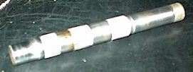
I had some problems cutting the rotor because of the hardness of the material used for the rotor. I went through 3 cutting bits during the process. I decided to try a different approach on the next one. I pressed the shaft off the old rotor unit completely and made another rotor out of a piece of 6061-T6 aircraft aluminum I had laying around. Although it seems like a bit more work ( starting from scratch ) it actually didn't take as long and I can use the same cutter on other projects also. Below is a picture of the shaft removed from the rotor and the aluminum rotor pressed on the shaft...
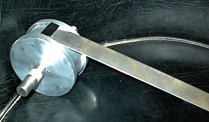
Most of the machining was done after the shaft was pressed into the new rotor. The next one shows the soft iron strip cut to fit the slot. The slot was cut deep enough to recess the magnets and the metal strip. The next picture shows the metal strip with a magnet laying in the groove
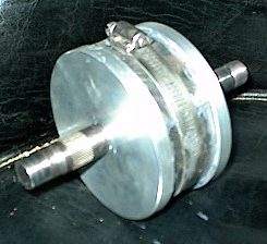
I roughed up the metal strip with a 20grit sanding disc ( paper with a rock glued to it - its pretty rough ). Then proceeded to glue the strip into place. I used a hose clamp to pull it in place and hold it until the epoxy set up. Actually put it in the oven at 150 degrees for an hour to help cure it a bit quicker.... worked well. The picture on the right shows the magnets in place and the spacing....
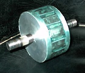
Below shows the magnets all glued in place and the rotor is ready to go back into the case....
After the new rotor was installed, the first tests came out quite good. Initially turning the rotor I noticed less cogging with the larger magnets. On the machine it showed 36.1 volts at 1500 rpm. It came up almost another volt from the first one. Amps were similar to the first. This one produced 50 amps at 1850 rpm. I rewound a stator with one size wire smaller and installed it in a case using this rotor and it now produces 50 volts at 1500 rpm but the output amps dropped ( give and take unfortunately ).
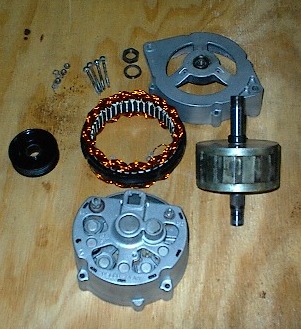
Above... all the parts to the completed unit and the unit completed Below is a comparison chart of the three units I've tested....
|