


|
|
|
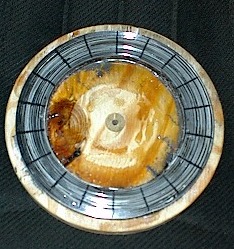
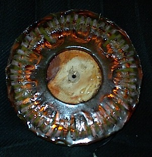
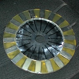
Scratch Built Axial Field Alternator I built this alternator from some emails I recieved about direct drive units and lowering the RPM per volt. I've done a few chain drive units that work well but they have their drawbacks. Problems relating to drive losses, they require higher winds to start, and have higher maintenance to name a few. My goal, once again, was to keep it as simple as possible so others could build one with basic tools and could be done relatively cheap. I believe what I have here accomplishes these goals. Since Radial flux type units require specificaly sized parts I chose the Axial Flux type. One of the things in the back of my mind was the "cogging" effect created by most of the PM alternators and the amount of wind it takes to start it. During the thought process for acomplishing this project I needed to either make it an "air core" or come up with a way to hand build an iron core. The "air core" type isn't very efficient in the sense that the coils aren't saturated properly when the magnets pass the coil. In order to cure this problem you would need 2 disc's with magnets on them. This would complicate the design so I started looking for other ideas. On first thought I pulled out a roll of mig welding wire and thought about rolling a "core" from this. Unfortuneately, this would require a special jig and a way to separate the wires from each other. I started looking at laminations from motors, transformers or what ever I thought would transfere flux fairly well. It dawned on me that sheet metal could be used in this part of the project. I cut strips of sheet metal and strips of cardboard and coiled them up until I had a piece the size that I needed. I used Fiberglass Resin to "laminate" the coil together then glued it to a 9" disc made from 3/4" plywood. Below shows the disc and laminations glued in place.
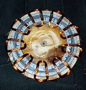
The steel coil was glued to the wood with JB weld then the fiberglass Resin poured over the steel core. The outside diameter of the steel core is 8" and inside diameter is 5.5". The magnets I chose was Item #27 from www.wondermagnet.com . I marked the stator at 20 degree intervals so there would be 18 magnets used on the rotor. The coils had to fit over the 20 degree area and in a trianglular form so I made a jig to make the coils. There is 27 coils to fill the rotor for a 3 phase set up. Each coil was 30 turns of #20 wire, and all made in the same direction. Below shows the coils of each phase being placed on the stator.
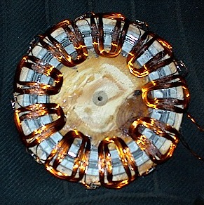
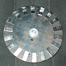
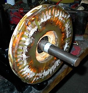
The initial tests of the single coil showed 1.1V at 630 rpm which meant I should get 9.9 Volts from the series of 9 coils. Testing showed 13.5V AC and 22V rectified which was much better than I had anticipated. I laid in all the other sets and soldered up all the connections in series for the last 2 phases of the alternator. This leaves 6 wires loose - 3 starts and 3 finishes to be wired up later. I used a hot glue gun to place the coils before finishing the stator. I reinstalled it on the lathe and started testing it with all the phases in place. In a "star" wiring it made 38 volts at 630 rpm and in a "Delta" wiring it made 22 volts. "Star" gives you more volts but less amps and "Delta" gives you more amps but less volts. I'll talk about the different wiring of it later. Below shows the Stator filled in with fiberglass resin. This seals the unit and holds the coils in place ... permanently! The other shows the steel disc the magnets are on for the rotor. None of them were glued on during the testing. They are quite strong and are very hard to move. The steel disc the magnets are on could be a disc cut out from plywood with a sheet metal disc laminated to the plywood disc. This would serve the same purpose. The steel behind the magnets intensifies the field going to the core and through the coils.
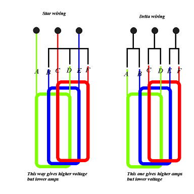
The magnet rotor will be mounted to the prop hub and the stator will be attatched to the bearing head. To complete the rotor the magnets are glued in place and resin will be poured onto the plate to lock them in forever then it will have to be balanced. Now to the wiring.... Here lies a problem, you can wire the alternator in a star configuration or in a Delta. The star gives you much more voltage but less amps and the Delta gives you less voltage and more amps. Below shows the way each of the three phases would be wired....
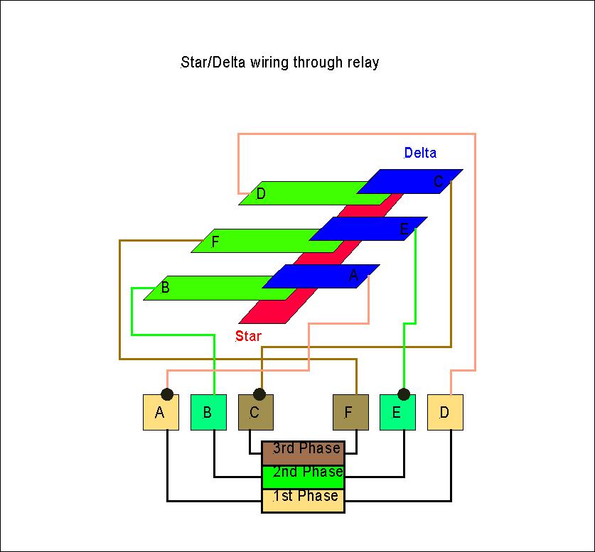
If this alternator is wired in the star configuration it will produce 217 watts at its highest rpm. In Delta could deliver up to 400 watts. Unfortunately, the delta configuration won't allow charging until it reaches 500 rpm which means our windmill wont charge until around 14mph. On the other end the star will give us 76 watts at that speed. It would seem the best solution would be to use them both. I have yet to figure out exactly how to do this.... any electronic genious's out there? I thought of using a relay that would kick in at a certain voltage... but as soon as the relay changes the voltage drops. You could use power mosfets for controlling the wiring change but how to control the transition.... either by using a hall sensor to keep tabs on the rpm.... or build a separate mini generator on the outer rim of the stator for low voltage input to the gate of the FET's.... still pondering that one.... any ideas welcome... send an email elenz(nospam)@windstuffnow.com (Remove "nospam") (See below on update for a wind driven relay system) After exerting many brain cells on this situation ( at least several that I know still work ) I started thinking of different approaches to this Star/Delta delema... First was a thought on an aircraft ASI ( air speed indicator), this uses a diaphram to exert pressure on the needle drive system through the use of a "pitot tube". Assuming you could figure out the size of tube and diaphram to exert the right amount of pressure at a certain wind speed to move the relay, this could work. The drawbacks to this system is the fact the pitot tube could get plugged with ice, snow, bugs etc... not such a good idea. Then down to my last couple cells I thought of using the wind (like the tail) to exert pressure on the relay at a certain windspeed. This seems to be the best I've come up with so far so I decided to go with it ... unless someone comes up with something better... remember it must be simple! Below is a diagram of how the relay would be wired
B,F,D are the moving contacts. A,C,E are the output lines. Once they are in contact with the red strip it would be in star configuration and when in contact with the blue strips its in Delta configuration. Make a mental note the 2nd phase of this alternator is reversed. This is because the phaseing is off when the coils are stacked in 3's. You still wind all the coils in the same direction and wire them all the same but the start and end wires are reversed. In any case... A small tail would (will) control the movement of the contacts. I haven't as yet built this unit and have no idea if it will even work as yet... its simply a plan... more on it later... Below is a chart of the calculated performance of this alternator. You can see where the star and delta should interchange for better output.
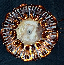
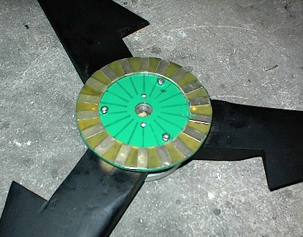
Below shows the magnet rotor after the Fiberglass resin was poured in around the magnets and the rotor mounted on the prop hub... The green is a rust resistant coating on all the steel parts that is exposed to the elements. The magnets are placed every 20 degrees and glued directly to the steel plate with aircraft epoxy. ( JB weld would work fine in this application). I used a coffee can lid (plastic) for the center and taped the outer edge of the steel plate to form a barrier to pour the Resin on. You want to make sure the rotor is level when you pour this or it will run to the low side.
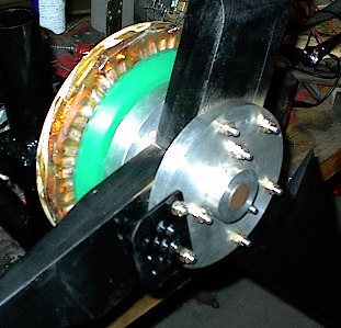
Below shows the stator on the bearing head and the prop on the unit. I still have some finishing up to do before it goes on the pole but the project has come to its final stages. I used a 6 ft prop with a TSR of 8 for this one. Shouldn't be any reason this unit won't produce 400 watts. The prop, during testing in a 20mph wind, leaped to 1000 rpm with no problem ( no load on it ). Very Very quiet too ! Also should start in fairly low winds because there is no restriction (such as cogging) until it comes up to speed to start charging.
|