

|
|
|
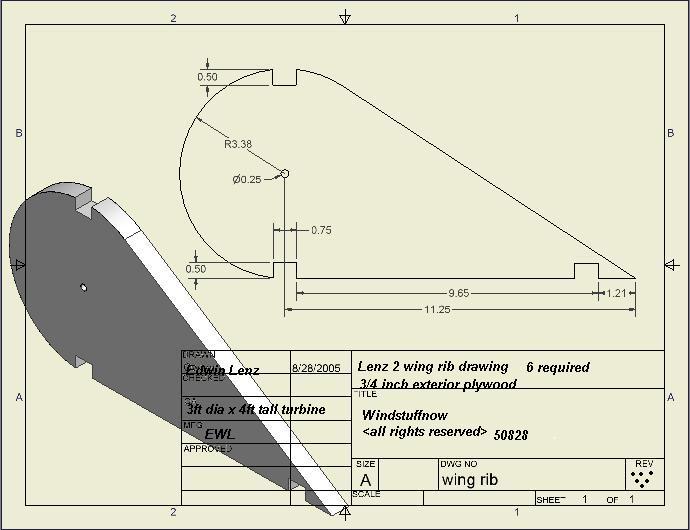
A few details for building the 3ft diameter x 4ft tall Lenz2 turbine... Below is a drawing for the wing ribs cut from 3/4" plywood.
NOTE: The above drawing shows that only 6 ribs are required, that should actually be 9 ribs required. I originally designed it with only the end ribs in place with a stiffener bracket in the center. The 3rd rib actually makes them much stronger. Wings...
The wings are basically built from 3/4" plywood for the ribs and the stringers were cut from treated 2x4's. The stringers are glued into the slots and later drilled for wood screws. Simply clamp the stringers into the slots and allow the glue to set. Once the glue has set you can cover the wings with aluminum sheet. I've also used PVC sheet in 1/8" thickness which might be cheaper than the aluminum. The aluminum sheet was .025 thickness and is actually lighter than the PVC sheet. Other light weight weather proof materials will work as well.
Above is another shot of the wing frame The rivets are aluminum 1/8" and are 3/4 to 1 inch long. I start by bending a 90 degree angle on the leading edge of the aluminum and rivet it to the top outer leading edge of the wing frame. Flip the wing over and roll the frame over the aluminum. Clamp it to the trailing edge. Start putting rivets evenly spaced around the nose through the aluminum into the wood ribs making sure the aluminum is pulled tight to the rib as you go.
When the aluminum is riveted to the frame bend the trailing edge to form a seal of sorts to the rear stringer. The alternator for the roof top model is simply a modified version of my 500 watt kit. The pdf instructions can be downloaded here . The differences are... the coils have 55 turns of #18 magnet wire and the stator is 1/4" thick instead of 1/2". NOTE: A more efficient stator can be made using 2 strands of 18 awg wire ( 15 awg equivalent ) , winding them for the 1/2" stator thickness. Follow the instructions for the 500 watt kit with the exception of the turns per coil. 2 strands of 18awg with 65 turns per coil ( or 15 awg single strand ). This will make the alternator more efficient in lower winds and add a better load to the turbine in higher winds and ultimately extract more power. Below is a picture of the alternator end of the turbine mounted to the 1 inch square tube frame...
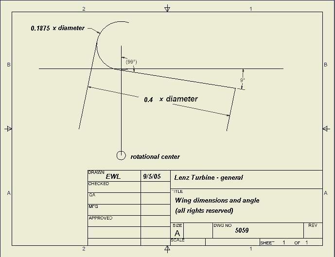
The magnets for the project can be purchased from my product page as well as the steel discs. The bearings used are standard 1 inch pillow block bearings purchase from Northern Tool ( best price I've found on them so far ). The frame for the turbine was made from standard 1x1 square steel tubing welded together to form a "box" shape with plenty of clearance on the sides. In the above picture you can see the two steel plates just above the bearing that is welded to the frame to hold the stator in place. The top and bottom magnet disc rotate and the stator simply sits centered in the air gap between them. Although it's shown in August 2007 Popular science on my roof, I don't recommend roof mounted turbines. I used this setting because it's very turbulent and it seemed like a good place to test it for this type of wind. It was also quick and easy as I was rushed while installing it in the late fall. The turbine will perform much better on a taller platform in clean un-turbulent air. It works very well where it's placed but it would perform much better and provide a higher more continuous output in a better location. Scaling the turbine and setting the wing angle is shown in the diagram below...
Below are some formula's to help find the rpm it might run in a given wind as well as how much power you might expect from the unit.... Watts output = .00508 x Area x windspeed^3 x efficiency Area in square feet ( height x width ) Windspeed in mph Example: the 3 x 4 described above in a 15 mph wind and an alternator of around 75% efficient would have a power output of ; .00508 x ( 3x4 ) x 15^3 x ( .41 x.75 ) = 63.26 watts Efficiency would vary depending on the alternator and building techniques. The turbine as tested will function at 41% efficiency at the shaft. The alternators efficiency will vary depending on the load. If you have an alternator performing at 90% and a turbine at 40% then the overall efficiency of the machine would be .9 x .4 = .36 or 36% efficient. If the alternator is only 50% efficient then the overall efficiency would be .5 x .4 = 20% . As you can see the alternator efficiency plays a big part in the overall efficiency or what you would see for charging. How large will it need to be to make a specific power output in a given wind... Watts / ( .00508 x windspeed^3 x efficiency) = total square feet of area Example: Lets say we want 63 watts in a 15 mph wind using the number from above; 63 watts / ( .00508 x 15^3 x (.75x.41)) = 11.94 sq ft ( or a 3ft diameter x 4 ft tall ) How fast will it run in a given wind speed... Windspeed x 88 / ( diameter x 3.14 ) x TSR Windspeed in mph diameter in feet the "88" is simply to convert the mph to feet per minute The TSR ( tip speed ratio ) for this machine for peak power is 0.8. Because it is a hybrid lift/drag machine in order for it to extract energy from both the upwind and downwind wings it needs to run slightly slower that the wind. 0.8 seems to be optimum while loaded although it will run at 1.6 unloaded. Example: The same turbine in a 15mph wind loaded to 0.8 TSR... 15mph x 88 / ( 3 x 3.14 ) x .8 = 112 rpm or unloaded - 15 x 88 / ( 3 x 3.14 ) x 1.6 = 224
Some things to consider when designing... if the alternator is weak the turbine will "run away" or overspeed in higher winds. It needs to be well balanced to handle these conditions or it could vibrate and cause something to break as well as burn up the alternator. It's better to overbuild the alternator slightly. You should incorporate a way to control the speed such as a shorting switch or break to slow it down and even stop it in high winds. The shorting switch is simply wired to your output wires from the alternator and shorts the alternator. This loads the turbine considerably, it won't stop it from turning but it will turn very slowly with that high load - here again this depends on the alternator in use. Since VAWT's can't be "furled" out of the wind they do need to be controlled. I've designed the turbine to work very well in low winds, and operate at much safer speed than some of it's counterparts. This wing design is very dirty in winds above 20mph and the efficiency drops off considerably in higher winds although it will continue to produce higher outputs as the wind speed increases. You are responsible for building and controlling the turbine, as with any wind machine mother nature can be cruel so build it strong and mount it well and you'll get years of use out of it... Have Fun! Play safe! If you'd rather buy this in kit form... www.WindGenKits.com is making a very nice Lenz2 Kit available with all the goodies available for building it from start to finish. They have also produced some very nice videos for building the stator and finishing it up. Everything you need for getting it up and running in short order... check them out !
|